Last Updated on: 13th June 2024, 07:59 pm
Part 3 – Interconnecting ‘old’ flat L2 based on EVPN/VXLAN network with a ‘new’ L3-BGP-only based one:
Motivation (for connecting ‘old’ BGP/EVPN network to ‘new’ L3-BGP-only)
- The old L2 network is overgrown and ARP tables on servers became very large. Scalability reached its limits.
- Migrating network architecture in place is impossible without re-deploying all servers.
- L3-BGP-only is the most obvious choice for future growth, but a new network needs a connection to the old one. We need to be able to keep CLOS topology (spine levels throughputs are in Tbps) to meet the latency and throughput demand.
Implementation
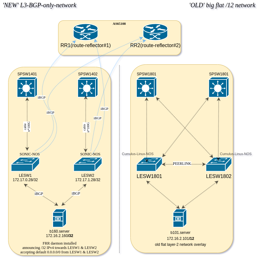
For each old L2 VLAN, we deploy a pair of route reflectors. These route reflectors will relay NLRI information between L2 servers and border SONiC L3 switches.
BGP route reflectors
BGP protocol is de-facto ubiquitous today. It was devised for ISP/IX/WAN but lately it started to be used on large LANs. There are 2 modes of BGP: eBGP and iBGP. eBGP is used between autonomous systems. iBGP is used inside the autonomous systems. We chose to implement iBGP for VLAN (in L2) / VRF (L3) and eBGP for routing between those separated internal networks. We can do that because traffic between internal networks is not large and we are filtering/firewalling it. Predefined-AS number is used for servers and switches included in the network (for VLAN in L2 or for VRF in L3). This way the network becomes a fully Autonomous System.
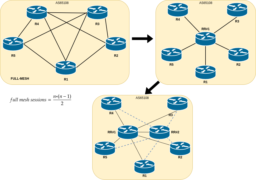
Usually iBGP requires full-mesh peering setup. With hundreds of servers in single VLAN scale, full-mesh topology would be impossible one to achieve. Full mesh connection formula is:
total number of connections = (n*(n-1))/2
n is the number of devices.
RR (Route Reflector) can propagate iBGP routes to peers, hence a full mesh of iBGP peers is not necessary. With network scaling-up, adding new peers will require only peering (SONiC Switches or L2 servers) with 2 x route reflectors. Both RR act as active ones (active-active solution) to provide redundancy along with multipath routes. Please be aware: route reflectors are not routers per se! They are only “reflecting” NLRIs (prefixes+attributes) to the connected clients – IP traffic is not forwarded nor passed by them directly. We use FRR demons to implement RRs.
Peering route reflectors between each other
# cat /etc/frr/frr.conf # <--- Click this to show moreThere needs to be intra-connection between pair of two route-reflectors to avoid split-brain case.
Peering RRs with SONiC LEAF gateways:
# cat /etc/frr/frr.conf # <--- Click this to show moreEach L3-BGP-enabled SONiC switch needs to be connected to the RR. We are using BGP-L3 peer group specifically for this purpose.
Peering old L2 hosts with RR:
# cat /etc/frr/frr.conf # <--- Click this to show moreEach old L2-based host needs to be peered with RR.
# cat /etc/frr/frr.conf # <--- Click this to show more for the whole config of RR:Please note that the whole FRR config includes optional kubernetes bits
Connecting ‘legacy-old’ servers to the RRs
Each server which is connected to the old big flat /12 network needs to peer with RR first, in order to be able to connect to the new L3-BGP-only-servers. When iBGP peering is established, route-reflector would advertise NLRIs to its client-peer without modifying attributes – the aim is to avoid routing loops. We have a smooth experience with a BIRD routing daemon – configuration file is human-readable and can be easily automated using tools such as Puppet or Ansbile.
Let’s consider 2 different servers:
- host b101 (172.16.2.101) is connected to the ‘old’ network with BIRD
- host b160 (172.16.2.160) is connected to the ‘new’ L3-BGP-network via SONiC NOS based SONiC LEAF#1 and LEAF#2 over FRR.
Let’s see how b101 sees b160.
# cat /etc/bird/bird.conf <--- click here to show more(ams)root@b101:~# birdc show protocol <--- click here to show moreb101# birdc show route count <--- click here to show moreAs you can see each ‘old’ server has a 2 iBGP sessions and it’s receiving over 722 NLRIs (prefixes+attributes).
These 722 prefixes include predominantely /32 IPv4 routes – for each ‘new’ L3-BGP-based-server is annoucing exactly 1 x IPv4 addr towards RRs.
BGP-table (also known as BGP topology table, BGP RIB) on ‘old’ servers is looking like this:
b101:~# birdc show route all for 172.16.2.160 <--- click here to show moreFIB-table (Forwarding Information Base) on the ‘old’ servers is looking like this:
b101:~# ip route show 172.16.2.160 <--- Click this to show morenext-hop 172.17.0.28 address is de-facto a Vlan2-interface configured on SONiC-based LEAF#1 while next-hop 172.17.1.28 address is de-facto a Vlan2-interface configured on SONiC-based LEAF#2.
Network path from b101 (server) to b160 (server) and the other way goes via SONiC LEAF:
b101:~# mtr -rwnc 10 172.16.2.160 <--- Click this to show moreb160:~# mtr -rwnc 10 b101Connecting ‘new’ L3-BGP-switches to the RRs
SONiC-enabled LEAFs (LESWs) are configured as follows.
Each odd-numbered leaf switch is connected directly via LACP portchannel to the odd-numbered spine switch e.g. LESW#1 to SPSW#1 and LESW#2 to SPSW#2 using multiple 100G interfaces. VLAN interface is assigned to the PortChannel0001 interface:
LESW1# show vlan brief <--- Click this to show moreLESW# SONIC config <--- Click this to show moreOn the other side (SPSW) of PortChannel we are extracting VXLAN to VLAN (Cumulus-Linux-NOS config):
auto lesw1
iface lesw1
	bond-slaves swp26 swp28
	bond-use-carrier 1
	bond-lacp-rate 1
	bond-lacp-bypass-allow 0
	mstpctl-portadminedge yes
	mstpctl-portbpdufilter yes
	bridge-pvid 1000
	bridge-vids 2 110 128
You can see VLANs configured on lesw1 below:
root@spsw1:mgmt-vrf:~# netshow vlan
VLAN    Flags     Interfaces
------  --------  ------------
2       Tagged    lesw1
        SVI       vlan2
        Untagged  vni-2
110     Tagged    lesw1
        SVI       vlan110
        Untagged  vni-110
128     Tagged    lesw1
        SVI       vlan128
        Untagged  vni-128
1000    Untagged  lesw1
As you can see this is demarcation point between old flat L2 EVPN-based network and the new L3-BGP-only based hosts.
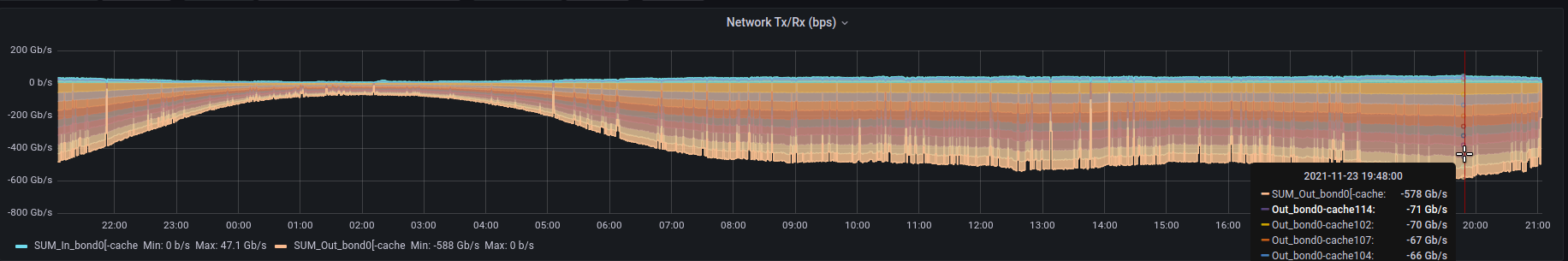
The amount of traffic is constatly growing and our setup allows scaling-up. We have interconnection consisting of 16x100Gbit/s ports coupled between each Spine and Leaf pair giving 3.2Tbit/s total BW – but please be aware that we can scale up as we grow! Now our biggest bandwidth-consuming DB cluster is using around 600Gbit/s at its peak and still growing! Each server of this cluster is serving flawlessly over 70Gbit/s TCP traffic!
show int portchannel
Flags: A - active, I - inactive, Up - up, Dw - Down, N/A - not available,
       S - selected, D - deselected, * - not synced
  No.  Team Dev         Protocol     Ports
-----  ---------------  -----------  -----------------------------------------------------------------------------------------------------------------------------------------------------------------------------------------------------------------------------------------------
 0001  PortChannel0001  LACP(A)(Up)  Ethernet172(S) Ethernet180(S) Ethernet188(S) Ethernet200(S) Ethernet152(S) Ethernet148(S) Ethernet164(S) Ethernet144(S) Ethernet184(S) Ethernet160(S) Ethernet176(S) Ethernet156(S) Ethernet192(S) Ethernet196(S) Ethernet168(S) Ethernet204(S)
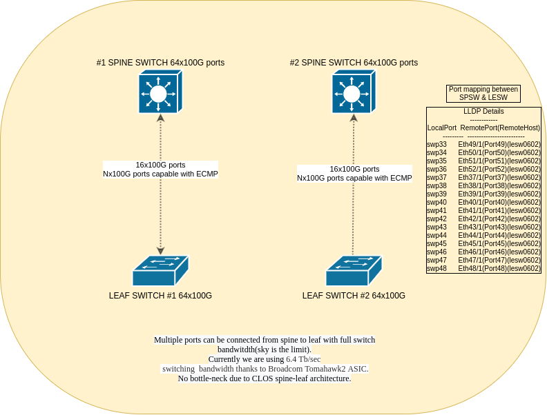
We are connecting spine and leaf with multiple 100G ports – currently each leaf is connected via 16x100G ports but the sky is the limit and de-facto switchport numbers! Interconnect can be done at any level: e.g. leaf to leaf, leaf to spine and leaf to super-spine – possible point of connection: anywhere (L2/L3 boundary). No bottle-neck due to CLOS spine-leaf architecture. A CLOS/Spine-Leaf or “fat tree” architecture features multiple connections between interconnection switches (spine switches) and access switches (leaf switches) to support high-performance computer clustering. In addition to flattening and scaling out Layer 2 networks at the edge, it also creates a nonblocking, low-latency fabric.
ECMP
Equal-cost multi-path routing (ECMP) is a routing feature where instead of traditional one next-hop exists per prefix there are multiple next-hops in use at the same time. Packet forwarding to a single destination takes place over multiple “best paths” in parralel simultaneously. The ECMP leverages modified Dijkstra’s algorithm to search for the shortest path, and uses the modulo-n hashing method in the selection of the delivery path. To prevent out of order packets, ECMP hashing is done on a per-flow basis, which means that all packets with the same source and destination IP addresses and the same source and destination ports always hash to the same next hop thus traffic will be uniformly spread across next-hops(load-balancing effect). Hashing is computed with 5-tuple:
- source IP address
- destination IP address
- protocol
- source port
- destination port
You can read more about hashing in excellent Broadcom document here.
Please note that BGP offers add-on called ADD-PATH described in RFC 7911 which is confusing – there terms are two different things! RTB House combines ADD-PATH and ECMP at the very same time – this two features help us leverage inter-DC network bottlenecks!
Below is example output of one IP (/32 prefix) which is fully-reachable over six next-hops:
172.16.64.31 proto bgp metric 20
	nexthop via 172.16.2.15 dev Vlan2 weight 1
	nexthop via 172.16.48.151 dev Vlan2 weight 1
	nexthop via 172.16.48.152 dev Vlan2 weight 1
	nexthop via 172.16.48.153 dev Vlan2 weight 1
	nexthop via 172.16.63.101 dev Vlan2 weight 1
	nexthop via 172.16.63.102 dev Vlan2 weight 1
BGP sessions status with Route-Reflectors <--- Click this to show moreFRR configuration snippet related to route reflectors connection through Spine portchannel:
#LESW1# show run bgp <--- Click this to show moreBGP neighbour output with route-reflector looking from SONiC point-of-view:
LESW# show ip bgp vrf Vrf2 neighbour 172.16.63.1 <--- Click this to show more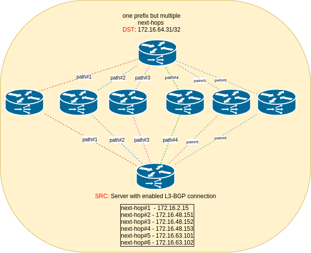
ARP refresher
Due to the unremedied SONiC interal bug we’ve implemeted workaround bash script called arp-refresher.sh which is started every 2 minutes in the background via crontab. Stale ARP is not refreshed by SONiC – it takes a hike from bridge (PortChannel) – then the servers in the “old” network are having issues connecting to the L3-BGP-only servers
root@lesw1:~# show arp | grep 172.16.21.116
172.16.21.116   0c:c4:7a:ea:7e:6e  -                2
root@lesw1:~# show mac | grep -i 0c:c4:7a:ea:7e:6e
As you can see from the syslog ARP refresher is doing it’s job properly:
lesw1:~# tail -f /var/log/syslog | grep arp <--- Click this to show moreYou can see the source code of arp-refresher.sh below:
/opt/rtb-network-sonic/share/bin# cat arp_refresher.sh This interconnection setup is working fine for over 2 months. We have critical services deployed on the servers that are prone to any distruption or latency-spikes in the network. After implementing ARP refresher SONiC works well for the setup described above on the Broadcom Tomahawk, Tomahawk II and Trident III ASICs.