Last Updated on: 13th June 2024, 08:01 pm
Part 2 – connecting a server to a router (switch) in L3
- Motivation (for server to switch connections design)
- Considerations
- Example scenario
- L3 Network layer ID/Separation
- BGP Unnumbered like – SONIC configuration
- Server side configuration (Linux – Debian/Ubuntu)
Motivation (for server to switch connections design)
- L2 network is growing and soon it will reach its limits. We need to start adding new servers in “L3” mode to avoid broadcasts and long ARP tables, but we would like to keep current features:
- servers need to be connected in redundant manner (one server to at least two switches), and – if possible – we would like to speed up fallback time
- we would like to keep clean network separation between bare-metal servers on network devices in L3, the same as we had using VLANs/VXLANs in L2
- “Server IP address” in L3 network should work the same as server IP address in old L2 network: server IP addres as endpoint for the connections to the deployed app
- we want to change switch’s NOS to more open and commonly used one. We have chosen SONiC. SONiC has less features than NOS that we are currently using. That is both advantage and disadvantage. Leass features means simpler configuration.
Considerations
For typical server deployment, during the network configuration, there are two tasks:
- assigning IP to server
- adding default gateway
It could be done automatically via DHCP or statically via server network configuration. The task is not easy when connecting multiple server interfaces to multiple routers (switches) in L3. The configuration will usually require:
- assigning IP(s) server “lo” interface
- each physical host need its own IP address
- some services (applications) need their own IP addresses because they use the same TCP listening ports as other services
- we use anycast in some of the distributed services and we need to configure the same IP address on multiple physical servers
- assigning an IP address for each server interface facing the router
- assigning an IP address for each GW/Peer
- routing daemon and routing configuration
Example scenario
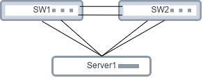
Let’s consider a scenario, where we have a server with four 25Gbps interfaces: eth0, eth1, eth2, eth3 and we are connecting it to the data center network in a redundant manner via two network devices: SW1 and SW2. When everything is working, the server has a 100Gbps connection to the network. When one of the switches is down, we can use only half of that.
L2/MLAG – typical traditional scenario and issues
In the typical/traditional approach the eth0, eth1, eth2 and eth3 interfaces on the server will be aggregated into a single interface (usually LACP group) via bonding or teaming and SW1 and SW2 switches must be configured in the MLAG cluster.
This kind of setup has some disadvantages:
- LACP does not fully verify the link’s state, so if for example RX link is blocked (single fiber cut in a dual fiber connection), the port will be up in the group in one direction and packets could be dropped on that link.
- LACP link down detection is slow (only two modes to choose from, in fast mode LACPDU packet is sent every second, Link is down after 3 frames are lost).
- MLAG cluster usually sacrifices few physical ports for peerlink between switches (depending on silicon chip).
- When the LACP port group is configured, you need to connect servers to the exact same ports in the group.
- From the switch MLAG cluster perspective, disaggregated LACP interfaces facing the server can not be configured as L3 (IP address can’t be assigned) and they need to be in the bridge (probably because MLAG+STP are closely connected in the implementation to avoid loops).
In this MLAG example scenario, network layer separation between servers could be achieved by adding MLAG interfaces to a separate VLANs.
L3 Network layer ID/Separation
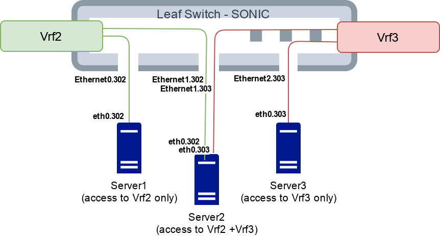
As mentioned in Part1 we intend to replace VLAN/VXLAN by VRF number as a network identifier, to implement network layer separations. Some of our servers may need to be in more than one network. For example a front server needs to be connected to the DMZ VLAN/VRF (network) and to the backend VLAN/VRF (network). In L3 we can create dedicated sub port for each Ethernet port on the switch device, then bind this sub port to the chosen VRF. The following example shows production network ID “2” and ID “3” that will be available to the servers on “302” and “303” sub port interface:
$ show vrf Vrf2 # <--- Click this to show moreEach production network will have a different unique pair of VRF and sub port number.
PXE/deploy network also has its own VRF, but since it requires native port, L3 interface needs to be terminated on Vlan, for example:
$ show vrf Vrf110
VRF     Interfaces
------  ------------
Vrf110  Vlan210
        Vlan110     # <- uplink, see part 3 of this blog series
$ show vlan brief # <--- Click this to show moreSONiC Gotchas
- In above setup we discovered that SONiC sometimes does not send “ARP who has” to default GW in PXE/deploy network. It could be caused by keepalived that we have configured on the default GW (keepalived is configured to periodically send GARP packets) or due to long inactivity (server’s untagged interface is used only for deployment and for rootfs decryption during boot). This issue can be mitigated by setting:
sysctl -w net.ipv4.conf.Vlan110.arp_accept=1on SONiC interface. - Configuration order seems to matter. So far we deployed “sub ports + untagged VLAN to the server” concept on Broadcom Tomahawk, Tomahawk 2 and Trident 3 based devices. Everything seems to work fine as long as untagged VLAN is configured last. For each setup change, we clear device configuration by
config realod, then we apply subport and vlan configuration in the right order. SONiC becomes more stable by each release, this issue may be already solved.
BGP Unnumbered like – SONIC configuration
BGP Unnumbered is a method to connect two (theoretically more is possible, but we did not find any implementation that supports it) BGP peers without the need to specify peer’s IP address. Part of it is based on rfc5549 and the rest is vendor specific. (Despite that the term “BGP Unnumbered” is widely used in the network industry, it has no RFC or standard, and some vendors may understand it differently.)
The idea behind BGP Unnumbered is to leverage IPv6 standard features to find a peer and establish BGP session:
- Link local IPv6 address creation on each interface, allows to automatically assign IP for both sides.
- Router Advertisements ICMPv6 packets allow to inform the other side what IP is assigned to the router and what IPv6 pool is available to the peers.
Routing demon then can discover peer IPv6 adddress on interface and using local IPv6 address starts BGP session. Then rfc5549 is implemented to advertise IPv4 Network Layer Reachability Information (NLRI) via this IPv6 BGP session between discovered peers.
IPv4 NLRI from the IPv6 peer needs a gateway. Since peer is IPv6, it could not be assigned as a gateway for IPv4, especially when switch silicon is not designed to handle that scenario. For example Cumulus Linux started implementing this by tricking the routing table to send packets through the correct interface:
# ip r
10.10.0.7  proto bgp  metric 20
	nexthop via 169.254.0.1  dev swp5 weight 1 onlink
	nexthop via 169.254.0.1  dev swp30 weight 1 onlink
	nexthop via 169.254.0.1  dev swp29 weight 1 onlink
	nexthop via 169.254.0.1  dev swp6 weight 1 onlink
	nexthop via 169.254.0.1  dev swp8 weight 1 onlink
	nexthop via 169.254.0.1  dev swp7 weight 1 onlink
10.10.0.8  proto bgp  metric 20
	nexthop via 169.254.0.1  dev swp5 weight 1 onlink
	nexthop via 169.254.0.1  dev swp30 weight 1 onlink
	nexthop via 169.254.0.1  dev swp29 weight 1 onlink
	nexthop via 169.254.0.1  dev swp6 weight 1 onlink
	nexthop via 169.254.0.1  dev swp8 weight 1 onlink
	nexthop via 169.254.0.1  dev swp7 weight 1 onlink
10.10.0.9  proto bgp  metric 20
	nexthop via 169.254.0.1  dev swp5 weight 1 onlink
	nexthop via 169.254.0.1  dev swp30 weight 1 onlink
	nexthop via 169.254.0.1  dev swp29 weight 1 onlink
	nexthop via 169.254.0.1  dev swp6 weight 1 onlink
	nexthop via 169.254.0.1  dev swp8 weight 1 onlink
	nexthop via 169.254.0.1  dev swp7 weight 1 onlink
...
and forcing right destination MAC address by placing it in neighbor table:
root@spsw1401:mgmt-vrf:~# ip n show | grep 169.254.0.1
169.254.0.1 dev swp4 lladdr 00:25:90:b2:a9:b0 PERMANENT
169.254.0.1 dev swp9 lladdr 00:25:90:b2:8f:7d PERMANENT
169.254.0.1 dev swp6 lladdr 00:25:90:b3:77:42 PERMANENT
169.254.0.1 dev swp24 lladdr 00:25:90:b2:82:d2 PERMANENT
169.254.0.1 dev swp21 lladdr 00:25:90:b2:ab:39 PERMANENT
169.254.0.1 dev swp10 lladdr 00:25:90:b2:8f:75 PERMANENT
169.254.0.1 dev swp3 lladdr 00:25:90:b2:a9:a8 PERMANENT
169.254.0.1 dev swp7 lladdr 00:25:90:b3:7d:e1 PERMANENT
169.254.0.1 dev swp20 lladdr 00:25:90:b2:97:28 PERMANENT
169.254.0.1 dev swp1 lladdr 00:25:90:b2:81:cc PERMANENT
169.254.0.1 dev swp8 lladdr 00:25:90:b3:7d:e9 PERMANENT
169.254.0.1 dev swp15 lladdr 00:25:90:b2:f1:91 PERMANENT
169.254.0.1 dev swp16 lladdr 00:25:90:b2:f1:89 PERMANENT
169.254.0.1 dev swp13 lladdr 00:25:90:b2:f1:da PERMANENT
169.254.0.1 dev swp11 lladdr 00:25:90:b2:ee:6e PERMANENT
...
Implementation with fixed “169.254.0.1” as a fake gateway is limiting BGP Unnumbered to only single peer (!) per interface. (Because even link local IP address must be unique per interface/network.)
On recent Linux kernels and latest FRR implementations, protocols were mixed by kernel developers (LoL):
$ ip r show
default nhid 2044 proto bgp metric 20
	nexthop via inet6 fe80::ae1f:6bff:fed5:9a04 dev eth0 weight 1
So forcing right destination MAC for 169.254.0.1 in neighbor table seems to be no longer required.
SONiC is forcing use of IPv6 global addresses on interfaces to establish IPv6 BGP session. Additionally, router advertisement (RA) could be sent only from link local IPv6 that was mapped to switch ASIC. Due to these limitations, it seems to be impossible to use BGP Unnumbered directly on sub port (at least we were unable to do so). We needed a workaround. We figured out that it is necessary to manually set both IPv6 Global and IPv6 link local addresses on each interface to allow SONiC to send RA and allow BGP session to be established over Global IPv6.
IPv6 address magic formula
IPv6 address formula for “fake BGP Unnumbered” interfaces was created to make assigning IPv6 addresses more manageable:
    ipv6="fc00:0000:${SUB_PORT_VLAN_NUMBER}:$(( ${ETH_NUMBER} + 1000 * ${SW_NUMBER} ))::1/64"
    llipv6="fe80:0000:${SUB_PORT_VLAN_NUMBER}:$(( ${ETH_NUMBER} + 1000 * ${SW_NUMBER} ))::1/64"
- SUB_PORT_VLAN_NUMBER: VLAN number that was assigned for the sub port interface, there is one number per VRF needed.
- ETH_NUMBER: Number of the Ethernet interface. Each IP address, even link local, need to be unique, so it could be applied to the switch ASIC.
- SW_NUMBER: ToR switch number. (It could be beneficial to have more than two ToR switches for N+1 redundancy).
- fc00::/7 – Unique local addresses.
Each interface has IPv6 addresses assigned by those SONiC CLI commands:
VRF=2
SUB_PORT_VLAN_NUMBER=$((300+$VRF)) # warning, interface name length is limited to 15 chars so SUB_PORT_VLAN_NUMBER should be short.

for E in ${SRV_PORTS[@]}
do
  ipv6="fc00:0000:${SUB_PORT_VLAN_NUMBER}:$(( ${ETH_NUMBER} + 1000 * ${SW_NUMBER} ))::1/64"
  llipv6="fe80:0000:${SUB_PORT_VLAN_NUMBER}:$(( ${ETH_NUMBER} + 1000 * ${SW_NUMBER} ))::1/64"

  config interface ip add Ethernet${E}.${SUB_PORT_VLAN_NUMBER} $ipv6 # subinterface creation
  config interface vrf bind Ethernet${E}.${SUB_PORT_VLAN_NUMBER} Vrf${EV} # VRF bind will clear subinterface IP, we need to set IP again
  config interface ip add Ethernet${E}.${SUB_PORT_VLAN_NUMBER} $llipv6
  config interface ip add Ethernet${E}.${SUB_PORT_VLAN_NUMBER} $ipv6
done
FRR config
For each sub port interface we need to configure FRR/zebra to send RA packets according to the IPv6 magic formula:
interface Ethernet0.302 vrf Vrf2
 ipv6 nd prefix fc00:0:302:1000::/64
 ipv6 nd ra-interval 5
 no ipv6 nd suppress-ra
!
interface Ethernet1.302 vrf Vrf2
 ipv6 nd prefix fc00:0:302:1001::/64
 ipv6 nd ra-interval 5
 no ipv6 nd suppress-ra
!
interface Ethernet10.302 vrf Vrf2
 ipv6 nd prefix fc00:0:302:1010::/64
 ipv6 nd ra-interval 5
 no ipv6 nd suppress-ra
!
interface Ethernet100.302 vrf Vrf2
 ipv6 nd prefix fc00:0:302:1100::/64
 ipv6 nd ra-interval 5
 no ipv6 nd suppress-ra
!
interface Ethernet104.302 vrf Vrf2
 ipv6 nd prefix fc00:0:302:1104::/64
 ipv6 nd ra-interval 5
 no ipv6 nd suppress-ra
!  ...
ipv6 nd prefix fc00:0:302:1100::/64: is advertising fc00:0:302:1100::/64 network for the clients to use. fc00:0:302:1100::1/64 will be on sub port interface according to magic formula that was mentioned above. Any other address in this network could be taken by the connected server.ipv6 nd ra-interval 5: increase rate for sending RA.no ipv6 nd suppress-ra: enabling zebra to send RA ICMPv6 frames on the interface.
For each VRF router we configure server group and listen range to allow any server that has acquired IPv6 from RA to establish BGP session on any interface:
router bgp 65108
!
router bgp 65108 vrf Vrf2
 bgp router-id 172.17.0.6
 bgp default show-hostname
 bgp cluster-id 172.17.0.6
 neighbor BGP-SERVERS peer-group
 neighbor BGP-SERVERS remote-as internal
 neighbor BGP-SERVERS description session to each host
 neighbor BGP-SERVERS bfd
 neighbor BGP-SERVERS capability extended-nexthop
 bgp listen range fc00:0:302::/48 peer-group BGP-SERVERS
 !
 address-family ipv4 unicast
  network 172.16.0.0/12
  neighbor BGP-SERVERS route-reflector-client
  neighbor BGP-SERVERS soft-reconfiguration inbound
  neighbor BGP-SERVERS prefix-list from-servers-prefixes in
  neighbor BGP-SERVERS prefix-list to-servers-prefixes out
 exit-address-family
!
ip prefix-list from-servers-prefixes seq 20 permit 172.16.0.0/12 ge 32
ip prefix-list from-servers-prefixes seq 500 deny any
ip prefix-list to-servers-prefixes seq 10 permit 0.0.0.0/0
ip prefix-list to-servers-prefixes seq 500 deny any
BGP summary
After establishing sessions, diagnosing/inspecting/finding interfaces is pretty straightforward:
show ip bgp vrf Vrf2 summary # <---- Click this to show the rest of content Server side configuration (Linux – Debian/Ubuntu)
Goals:
- identical config on all server hardware
- minimal network configuration requirements:
- hostname
- IPv4 address to advertise
- sub port interface id/number to select the network VRF
In our opinion it is good practice to get rid of new kernel/systemd interface names, so interface names on each type of hardware is identical. Usually it is done by adding kernel parameters:
net.ifnames=0 biosdevname=0
/etc/network/interfaces
We accommodate config for servers that have up to eight network interfaces, any of the interfaces can be connected to the switch. IPv4 server address is assigned to lo:101. IPv6 addresses for BGP sessions etc. are assigned to 302 sub port on every physical interface by RA. Below you can find configuration example:
$ cat /etc/network/interfaces # <--- Click this to show content LLDP BGP peer discovery replacement
It would be nice to have native LLDP Peer Discovery. Unfortunately, this feature has not been implemented yet. We decided to write simple scripts based on lldpd linux package to discover server peers. Here is a current PoC that we are working on.
Service monitors LLDP changes and writes all detected BGP peers to /etc/rtbbgp/peers.
$ systemctl status lldp-peer-dicovery.service
● lldp-peer-dicovery.service - LLDP discovery bgp peers https://dokuwiki.rtbhouse.net/dokuwiki/doku.php?id=devel:admin:l3-sonic-migration-propsal&#peer_discovery
     Loaded: loaded (/etc/systemd/system/lldp-peer-dicovery.service; enabled; vendor preset: enabled)
     Active: active (running) since Tue 2021-08-24 08:16:24 UTC; 2 weeks 6 days ago
   Main PID: 2990 (lldp_peer_dicov)
      Tasks: 4 (limit: 154285)
     Memory: 1.5M
     CGroup: /system.slice/lldp-peer-dicovery.service
             ├─2990 /bin/bash /opt/puppet-files/admin-tools/rtbbgp/bin/lldp_peer_dicovery.sh
             ├─2994 /bin/bash /opt/puppet-files/admin-tools/rtbbgp/bin/lldp_peer_dicovery.sh
             ├─2995 /bin/bash /opt/puppet-files/admin-tools/rtbbgp/bin/lldp_peer_dicovery.sh
             └─3061 lldpcli -f keyvalue watch
$ cat /etc/systemd/system/lldp-peer-dicovery.service
[Unit]
Description=LLDP discovery BGP peers https://dokuwiki.rtbhouse.net/dokuwiki/doku.php?id=devel:admin:l3-sonic-migration-propsal&#peer_discovery
After=lldpd.service
BindsTo=lldpd.service

[Service]
ExecStart=/opt/puppet-files/admin-tools/rtbbgp/bin/lldp_peer_dicovery.sh
Restart=on-failure

[Install]
WantedBy=multi-user.target
$ cat /opt/puppet-files/admin-tools/rtbbgp/bin/lldp_peer_dicovery.sh # <--- Click this to show content Server FRR – config generator
Servers have simple FRR configuration generator script. Additional systemd service will generate and reload FRR config every time a new peer is added to /etc/rtbbgp/peers. As long as switch has IPv6 configured on sub ports according to the magic formula, server connection can be physically moved (online) between ports or even devices. (It is a nice fature to have, if remote hands are not careful in data center. ?)
$ systemctl status frr-reload.path
● frr-reload.path - Look for changes in dir and run service
     Loaded: loaded (/etc/systemd/system/frr-reload.path; enabled; vendor preset: enabled)
     Active: active (waiting) since Tue 2021-08-24 08:16:22 UTC; 2 weeks 6 days ago
   Triggers: ● frr-reload.service
$ systemctl status frr-reload.service
● frr-reload.service - Build config and reload frr service
     Loaded: loaded (/etc/systemd/system/frr-reload.service; enabled; vendor preset: enabled)
     Active: inactive (dead) since Tue 2021-08-24 08:16:25 UTC; 2 weeks 6 days ago
TriggeredBy: ● frr-reload.path
   Main PID: 2901 (code=exited, status=0/SUCCESS)
$ cat /etc/systemd/system/frr-reload.path
[Unit]
Description=Look for changes in dir and run service

[Path]
PathModified=/etc/rtbbgp/peers/

[Install]
WantedBy=multi-user.target
$ cat /etc/systemd/system/frr-reload.service
[Unit]
Description=Build config and reload frr service
After=frr.service
BindsTo=frr.service

[Service]
ExecStart=/opt/puppet-files/admin-tools/rtbbgp/bin/frr-reload.sh

[Install]
WantedBy=multi-user.target
$ cat /opt/puppet-files/admin-tools/rtbbgp/bin/frr-reload.sh # <--- Click this to show script content FRR config highlights:
route-map EXPORTLO: will discover lo addresses and advertise them to the switches. You can add/remove lo addresses at the runtime and they will be discovered and advertised.multipath-relax: Enables ECMP.
Final result on server side
Example server routing table (four interfaces connected):
# ip r
default nhid 4223 proto bgp metric 20
	nexthop via inet6 fc00:0:302:2036::1 dev eth2.302 weight 1
	nexthop via inet6 fc00:0:302:2040::1 dev eth0.302 weight 1
	nexthop via inet6 fc00:0:302:1036::1 dev eth3.302 weight 1
	nexthop via inet6 fc00:0:302:1040::1 dev eth1.302 weight 1
169.254.111.0/24 dev docker0 proto kernel scope link src 169.254.111.1 linkdown
$ ip a # <--- Click this to show content $ ip n # <--- Click this to show content BGP sessions:
b109.creativecdn.net# show ip bgp summ

IPv4 Unicast Summary:
BGP router identifier 172.16.2.109, local AS number 65108 vrf-id 0
BGP table version 514
RIB entries 2, using 384 bytes of memory
Peers 4, using 85 KiB of memory
Peer groups 1, using 64 bytes of memory

Neighbor                                V         AS   MsgRcvd   MsgSent   TblVer  InQ OutQ  Up/Down State/PfxRcd   PfxSnt
lesw2801(fc00:0:302:1036::1)            4      65108   4773515   4773501        0    0    0 07:32:56            1        1
lesw2801(fc00:0:302:1040::1)            4      65108   4773426   4773409        0    0    0 06:04:56            1        1
lesw2802.deploy.lan(fc00:0:302:2036::1) 4      65108   3973826   3973824        0    0    0 02w5d07h            1        1
lesw2802.deploy.lan(fc00:0:302:2040::1) 4      65108   3973791   3973786        0    0    0 02w5d07h            1        1

Total number of neighbors 4
b109.creativecdn.net# show ip bgp ipv4 neighbors lesw2801 received-routes
BGP table version is 514, local router ID is 172.16.2.109, vrf id 0
Default local pref 100, local AS 65108
Status codes:  s suppressed, d damped, h history, * valid, > best, = multipath,
               i internal, r RIB-failure, S Stale, R Removed
Nexthop codes: @NNN nexthop's vrf id, < announce-nh-self
Origin codes:  i - IGP, e - EGP, ? - incomplete

   Network          Next Hop            Metric LocPrf Weight Path
*> 0.0.0.0/0        fc00:0:302:1036::1
                                             0    150      0 204995 i

Total number of prefixes 1
b109.creativecdn.net# show ip bgp ipv4 neighbors lesw2801 advertised-routes
BGP table version is 514, local router ID is 172.16.2.109, vrf id 0
Default local pref 100, local AS 65108
Status codes:  s suppressed, d damped, h history, * valid, > best, = multipath,
               i internal, r RIB-failure, S Stale, R Removed
Nexthop codes: @NNN nexthop's vrf id, < announce-nh-self
Origin codes:  i - IGP, e - EGP, ? - incomplete

   Network          Next Hop            Metric LocPrf Weight Path
*> 172.16.2.109/32  0.0.0.0                  0    100  32768 ?

Total number of prefixes 1
Nice unexpected features
Docker default network/NAT is working perfectly fine and does not require any additional changes on the system
Please continue to the next post, if you want to find more about how we connected those L3 SONiC switches to the old EVPN/BGP network.